
Download Now: Best Practice: Structural Engineering for Composite Substructure Materials – Composite Metal Hybrid (CMH) vs. Generic FRP for Cladding Support of Exterior Walls’ Engineering Study
The state of the art for thermally broken cladding support attachments has improved over the last several years. High-performance CMH, a composite metal hybrid material, and, more recently, generic fiber-reinforced polymer (FRP) Z sections are available as thermally efficient continuous insulation system components. The purpose of this study is to review the structural performance of these products relative to (1) best practice procedures for structural analysis and (2) standard wall loading conditions.
In the drive for thermally efficient continuous insulation systems, it is critical to maintain or improve the engineering, structural, and durability characteristics of the thermally efficient product. As is shown in the data contained in this paper, that is not always the case.
Material Selection – Generic FRP vs. Steel vs. CMH
The Difference
FRP composites have been used structurally since World War II, but unlike steel, their design practices are still evolving. Structural steel relies on standardized codes worldwide, while FRP design depends on manufacturer-specific methods, which vary widely and hinder consistent adoption.
Steel is homogeneous and isotropic, with uniform properties in all directions. FRP, however, is orthotropic—its strength and stiffness vary along each axis (x, y, and z), depending on fiber orientation—making analysis more complex.
FRP can also be tailored by adjusting resins, fibers, fillers, pigments, and proportions, creating materials with unique properties. This flexibility allows for customization but adds variability to design practices.
Advantages of FRP over steel include:
Superior thermal properties
Lighter weight and reduced transport costs
Customizable through pultrusion
Corrosion resistance
Ease of cutting and drilling
Advantages of steel include:
Higher modulus of elasticity
Faster, more reliable fastening with screws
Greater durability, torque retention, and pull-out strength
To leverage both materials, Composite Metal Hybrid (CMH) technology integrates a continuous steel insert within the FRP flange of a thermoset Z-profile. This enables the use of steel screws for cladding attachment, creating a hybrid system that combines the strengths of both materials, as shown in Image 1.
Benefits of Composite Metal Hybrid: Best of Both Worlds
How Steel and FRP are Made and Why Third-Party Validation is Important
Humans have used iron for millennia, and modern steel production is highly systematic, ensuring consistent, predictable quality.
By contrast, FRP pultrusion has only been practiced for about seven decades. A typical pultrusion manufacturing process is depicted in Image 2.

The pultrusion process: how FRP materials are typically manufactured.
Each manufacturer uses proprietary processes that evolve with new technologies, leading to non-standardized methods. Because of this variability, rigorous quality assurance and quality control (QA/QC) are critical to ensure FRP products meet design intentions, deliver the expected engineering properties, and minimize performance variations.
A successful FRP QA/QC program should include at minimum:
A well-documented and regularly updated quality control manual with logs of all procedures and tests.
Third-party evaluation, review, and approval of published engineering data.
Third-party inspection certification of the QA/QC program, compliant with ISO 17020.
Physical Properties of FRP
FRP is highly versatile and can be engineered with custom properties, which must be defined through agreement between the engineer and manufacturer.
The physical and mechanical properties of pultruded FRP depend on the type of thermoset resin, glass fibers, and the mix ratio of fibers, filler, and other constituents, with a minimum fiber content of 30% by volume.
FRP components are characterized by two main directions:
Longitudinal (lengthwise): Along the component’s main axis, where fibers are typically continuous.
Transversal (crosswise): Perpendicular to the longitudinal axis.
For Z-girts carrying cladding loads on exterior walls, tensile strength in the longitudinal direction is the critical design factor (see Table 1).
Table 1: Typical Minimum Mechanical Properties
Mechanical Property | CMH | ASTM Test Method | Generic FRP |
| Longitudinal Tensile Strength | 50,000 psi* | D638 | 30,000 psi
|
| Transverse Tensile Strength | 40,000 psi | D638 | 10,000 psi |
| Longitudinal Tensile Modulus | 29,000,000 psi* | D638 | 2,500,000 psi |
| Transverse Tensile Modulus | 3,300,000 psi | D638 | 800,000 psi |
*Longitudinal properties represent 16 ga. (50 KSI) steel insert | |||
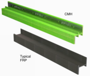
A side-by-side comparison of a CMH Z-girt and an FRP-only Z-girt.
Joinery Methods for Steel, CMH, and FRP Z-Girts
The girt lateral joinery detail is required for structural calculations when installing girts horizontally over vertical studs—the most common wall configuration.
Typical solutions include:
Steel Z-Girts:
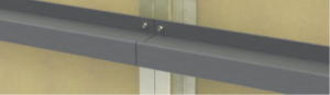
- Lap Joint: Steel Z-girts, typically thin (≈0.062″) but stiff (high modulus of elasticity), can be easily lapped and stitched together (Image 3).
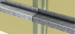
Steel Lap Joint
CMH Z-Girts:
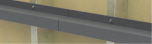
- Interlocking Joint: Composite metal hybrid Z-girts use an integral interlock system that connects one girt end to the next (Image 4).

The integral interlocking system of a composite metal hybrid Z-girt.
FRP Z-Girts:
Two possible joinery methods for FRP Z-girts include:
- Butt Joint: Each girt end rests on half of a 1.5″ stud. This is not recommended due to ASCE fastener margin requirements (2.125″ minimum flange width). Using this method would require double studs at every girt joint (Image 5).
FRP Butt Joint
- Cantilever: Girts are installed with cantilevered ends over studs (Image 6). For calculations, use the maximum cantilever as the worst-case condition. This is the only practical solution at present.
FRP Cantilever
Cladding/Substrate Attachment Methods
Cladding attachment methods vary in effectiveness across systems:
- Steel Girts: Traditional steel Z-girts use self-drilling fasteners for reliable attachment to both cladding and substrate.
- CMH Girts: CMH incorporates a continuous metal insert, also using self-drilling fasteners with pullout, shear, and strength values equal to steel. Fastening through the FRP into steel further strengthens the profile.
Generic FRP Girts: The FRP industry data does not recommend screws as a best practice for structural attachment. Potential liabilities include the following:
- Singularity points for stress are created, which weakens the section
- Discontinuity in the fibers weakens the section
- The discontinuity in the matrix is prone to crack propagation and fracture
- Torque resistance of the screw into FRP deteriorates with time
- Ability for load retention in case of fire is reduced
- Reduced fastener pullout values and retention performance
Bolted connections remain the best practice for structural integrity. Fasteners into substrate are less problematic, but calculations must account for potential pull-through if flanges are thin, fastener heads small, or installation uneven.
Safety Factors
Safety factors compare maximum material strength to maximum stress in a given direction. FRP manufacturers often use high safety factors to account for variability and additional influences such as:
High service temperatures (>190°F in cavities)
Creep and material aging
Cyclic loading and environmental effects
Notches, holes, and minor damage
Missing or stripped fasteners
This paper uses a reference safety factor of 4. However, ASCE’s Design Guide for FRP Composite Connections notes this may exclude environmental effects. A2P generally recommends a minimum factor of 6, depending on product and application. *
*Mosallam, Ayman S. “Design Guide for FRP Composite Connections,” ASCE Manuals and Reports on Engineering Practice No. 102. 2011.
Structural Analysis of Sub-Framing Z-Girts
Z-girts are widely used for supporting cladding and insulation because:
Flange access allows connection without thermal bridging.
Insulation discontinuity is limited to the web thickness, enabling continuous insulation.
However, their analysis is complex. The Z-shape’s asymmetry and eccentric load paths create torsional and warping stresses, making hand calculations unreliable. Accurate results require Finite Element Analysis (FEA) with detailed 3D geometry, precise load application at fastener points, and correct end condition modeling. Without advanced FEA, even experienced engineers risk overlooking critical stress effects.
Best Practices for Z-Girt Stress Analysis
Model loads as point loads at fastener locations; uniform loading underestimates stresses and deflections.
Consider both positive and negative lateral loads, as results vary greatly due to asymmetry.
Avoid simplified hand calculations that ignore eccentricity; use 3D FEA with exact geometry and load placement.
Correctly model end conditions, especially when girts are cantilevered between supports, as these often govern design.
Evaluate both stress and deflection. A girt that meets stress limits but fails deflection—or vice versa—is considered a structural failure.
See the Appendix for information on how to run FEA modeling accurately, including settings, orthotropic analysis, point loading, and more.
Description of Materials Tested
| CMH | GENERIC FRP | |
| Approximate Dimensions | Approximate Dimensions | |
| Exterior Flange Height | 1.5″ | 2″ |
| Exterior Flange Thickness | 0.2″ * | 0.25″ |
| Web Thickness | 0.105″ | 0.15″ |
| Interior Flange Height | 1.75″ | 2″ |
| Interior Flange Thickness | 0.2″ * | 0.15″ |
| Modeled Girt/Insulation Depths | 2″, 2.5″, 3″, 3.5″, 4″ ** | 2″, 2.5″, 3″, 3.5″, 4″ ** |
| *Dimension includes 16 ga. (50 KSI) steel insert **Dimensions on generic FRP girt are .4″ deeper to accept standard insulation sizes | ||
Description of Testing Parameters
Parameters for orientation, spacing, and loading utilized in the Finite Element Analysis (FEA) represent typical wall assembly scenarios.
FEA Stress Analysis Comparison of CMH and Generic FRP
Two types of FEA stress analyses will be analyzed herein: supported on both ends and cantilevered. The FEA results and discussion utilizing CMH and FRP will be shown with girt/insulation depths of 2″, 2.5″, 3″, 3.5″, and 4″ with fixed parameters of the simulations as shown in Table 2.
Table 2: FEA Parameters
| Case 1: Studs 16” OC with cantilever | Case 2: Studs 16” OC, no cantilever | Case 3: Studs 24” OC, no cantilever | Case 4: Studs 24” OC, with cantilever* | |
| Simulation parameter description | Fixed-parameter value(s) | Fixed-parameter value(s) | Fixed-parameter value(s) | Fixed-parameter value(s) |
| Span of girt substrate support | 16″ | 16″ | 24″ | 24″ |
| Vertical spacing of girts | 24″ | 24″ | 24″ | 16″ |
| Orientation of girts | Horizontal | Horizontal | Horizontal | Horizontal |
| Spacing of cladding fastener (point loads spacing) | 16″ | 16″ | 16″ | 16″ |
| End conditions of each 8-footer girt | Cantilever | Both ends supported | Both ends supported | Cantilever |
| Maximum cantilevered distance of the girt | 15″ | N/A | N/A | 23″ |
| Location of the cantilever load | 1 inch from end | N/A | 1 inch from end | |
| Cladding dead load | 5 PSF | 5 PSF | 5 PSF | 5 PSF |
| (*) Stress and deflection for the 23“ cantilever for the FRP exceeded the FEA parameters of the generic FRP material for 2.5“ through 4“ for the positive wind pressures, so the rest of the data was extrapolated for positive wind pressure. | ||||
Table 3: Material Properties of CMH and Generic FRP
| Material Property | CMH | Generic FRP |
| Longitudinal Max Stress | 50 KSI * | 30 KSI |
| Transversal Max Stress | 40 KSI | 10 KSI |
| Longitudinal Modulus of Elasticity | 29,000 KSI * | 2,500 KSI |
| Transversal Modulus of Elasticity | 3,300 KSI | 800 KSI |
| *Longitudinal properties include 16 ga. (50 KSI) steel insert | ||
Loading Conditions
The wind loads selected are typical components and cladding values for mid-sized buildings. The cladding dead load of 5 PSF encompasses the majority of cladding selections, including metal panels, ACM, fiber cement, and phenolic panels, among others.
The wind loads in the study are +40 PSF and -70 PSF ultimate wind pressures, with positive pushing inward toward the inside of the building and negative pulling outward away from the building. The controlling load combinations per ASCE 7-10 and International Building Code 2015 are D + 0.6 * W for stress and D + 0.42 * W for deflection.
Wind and dead loads are applied as a point load at the attachment point. The steel in the CMH is not included in the results as it maintains a safety factor of 4 in all cases.
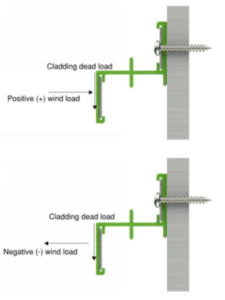
Directions of Wind and Dead Loads
FEA Modeling
Results and Discussion, Case I
Based on the parameters from Table 3, the FEA stress analysis results are shown in the following pages for each of the types of Z-girts (CMH and generic FRP) and for the different sizes and wind pressures.
As evidenced by the data, the FEA simulation results show the generic FRP section will not work for the input loading of cladding weights and wind pressures, as its stress safety factors are generally less than what is acceptable for a safe design, typically 4 or larger.
FEA stress analysis of the CMH shows an acceptable stress safety factor that is, in general, larger than 6 and always more than 4.
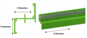
Schematic of GreenGirt CMH™ Z-Girt
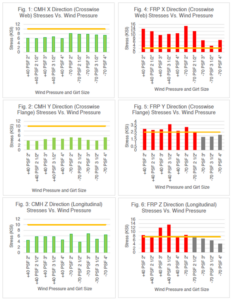
A comparison between CMH and FRP for directional stress is shown in Fig. 1 – 6. The stress level corresponding to a safety factor of 4 is shown by a horizontal line. In Fig. 1 – 6, whenever a stress level breaks through the safety factor line, that indicates the material performance for stress does not meet the design criteria for an acceptable safety factor, and such material shall not be used. For comparison of the two materials’ performance, the FRP figures are shown on the right side of the page, while the CMH figures are shown on the left. None of the CMH cases cross the safety factor line; however, most of the FRP cases cross the safety factor horizontal line.
Fig. 1 and 4 show the maximum x-direction stresses, and it indicates that the FRP girt stresses are larger than the maximum stresses developed for CMH girts in all but three of the 10 loading cases. The FRP stresses are about 50% larger than those of the CMH. The three cases in which the FRP stresses are lower than CMH correspond to the negative wind pressure for the 3″, 3.5″, and 4″ girts. The negative pressure loading cases do not control the design as the stress produced by these cases is lower than those produced by positive pressure, as seen in Image 7. The reason for this is negative pressure counteracts any eccentricity effect of dead loading, while a positive pressure will magnify the eccentricity effects of the dead loads. That is why a 40 PSF positive pressure produces higher stresses than a 70 PSF negative pressure for the same cladding dead weight and the same girt geometry.
The same conclusion regarding the x stresses is applicable to the y-direction stresses and the z-direction stresses (Fig. 2, 5, 3, 6).
In the data presented herein, the z-direction is the main longitudinal direction along the girt. Fig. 3 and 6 show the FRP girt stresses are much larger than the CMH girts, except for the three cases previously mentioned. For the same reason as above, these three cases do not control the stress design as their values are smaller than those of the positive wind pressure cases.
The only directional stress that is larger in all cases for CMH than the generic FRP sections is the Y-directional stress, which is crosswise (transversal direction) on the flange. However, the CMH strength in the transversal direction is 40 KSI, while that of the FRP section is 10 KSI. This makes the safety factors for the CMH case larger than 6 for all cases, while the safety factors for the FRP cases fail to meet the minimum 4 benchmark in seven out of 10 cases, as evidenced by the stress levels of the FRP sections crossing the horizontal safety factor line in Fig. 5.
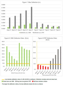
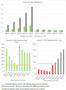
The deflection ratios in most cases for the generic FRP Z- girts will not meet common practice deflection criteria for exterior wall applications, as set by the building codes. For metal flexible cladding type with a required span-to-deflection ratio of 90 or better (45 for a cantilever, as 2L/x is used for a cantilevered member), the generic FRP Z-girts fail to meet the criteria of serviceability, so it will also not meet the deflection criteria for brittle types of cladding which require larger span to deflection ratio performance.5, 6
A deflection comparison between CMH and FRP in all the cases studied is shown in Fig. 7 – 9. The deflection of the generic FRP cases is large and fails to meet reasonable exterior wall applications in six out of ten cases. However, the four cases with acceptable deflection levels are related to the 70 PSF negative pressure, and these same girts have larger deflection for the 40 PSF positive wind load. All generic FRP girts fail the design criteria with respect to deflection and cannot be accepted as supports for cladding and insulation in building exterior wall applications. The same argument can be made with respect to the span-to-deflection ratios shown in Fig. 9, as all five girts fail the design criteria by having a span-to-deflection ratio less than 90 (or 45 for a cantilever).
In all cases, the CMH deflection is low and acceptable. The CMH Z-girt deflection ratio makes it suitable for supporting most cladding types.
Deflection criteria are typically called out in the specification for each cladding, as shown in Table 4.6. Deflection includes both wind load and dead load per criteria called out in the International Building Code load combinations.
Table 4: Typical Deflection Criteria by Cladding Type
| Cladding Type | Typical Deflection Criteria |
| Corrugated metal panels | L/90* or L/120 |
| Fiber cement siding | L/120 |
| ACM/MCM and concealed fastener metal panels | L/180 or L/240 |
| Fiber cement panels | L/240 |
| Stucco, terra cotta, and thin brick | L/360 |
| Masonry (brick, stone, etc.) | L/600 |
| * While Table 1604.3 of the International Building Code gives a minimum of L/120 for deflection limits, footnote A provides L/90 for secondary wall members supporting formed metal siding. | |
Stresses for Case I (16″ span, 24″ spacing, 15″ cantilever) with CMH and Generic FRP
![]()
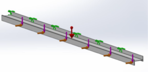
Deflection for Case I (16″ span, 24″ spacing, 15″ cantilever) with CMH and Generic FRP
Results and Discussion, Case II
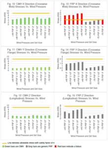
This case covers the Z-girt span condition 16″ with the girt ends supported (no cantilever). Although this case is the least demanding case for performance compared to all other cases in this study – due to the lower span and no cantilever condition – the results, as shown in Fig. 10-15, show that the FRP girts have a stress safety factor less than the minimum of four in the x-crosswise direction, while the CMH Z-girts meet the minimum safety factor of four in all directions and girt sizes.
Also, the deflection ratios for the CMH Z-girts are above the minimum of 90 for all girt sizes and in most cases, greater than 260.
However, the deflection ratios of the FRP Z-girts are less than the minimum of 90 for the girt sizes of 3″, 3.5″, and 4″.
In summary, even though this case has the lowest span and a no-cantilever end condition, the FRP girts failed to meet the minimum requirements for stress safety factor and deflection ratio.
See the Appendix for further data.
Stresses for Case II (16″ span, 24″ spacing, no cantilever) with CMH and Generic FRP
See Image 8 for an explanation of X, Y, and Z directions
Deflection for Case II (16″ span, 24″ spacing, no cantilever) with CMH and Generic FRP
Results and Discussion, Case III
In these FEA stress analysis models, the end of the girts are simply supported and do not cantilever.
The model parameters are shown in Table 3, and the same material properties are used as in Case I. However, in the Case III models, the unsupported span of the girts was increased to 24 inches (corresponding to a substrate/stud spacing of 24 inches).
As in Case I, the FEA simulation results were for five different girt sizes using generic FRP and CMH types. The girt depths are 2″, 2.5″, 3″, 3.5″, and 4″.
Case III results are presented in Fig. 19 – 27.
Both Cases I and III results and discussions provide similar trends of behavior for the girts. Furthermore, the discussions and conclusions indicated in Case I are also true for Case III.
See the Appendix for further data.
Stresses for Case III (24″ span, 24″ spacing, no cantilever) with CMH and Generic FRP
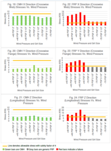
See Image 8 for an explanation of X, Y, and Z directions
Deflection for Case III (24″ span, 24″ spacing, no cantilever) with CMH and Generic FRP
Results and Discussion, Case IV
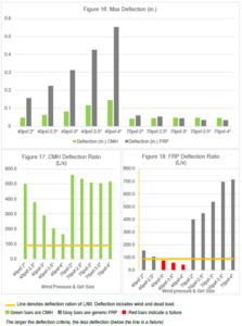
Of all the cases considered in this study, this case has the most severe loading conditions. There is a larger performance demand on the modeled girts due to the wider span of 24 inches and the cantilever distance of 23 inches.
All CMH Z-girts met the minimum requirements of stress safety factors of four in all directions.
The FRP Z-girts had, in most cases, stresses larger than the minimum allowed with a safety factor of four. Furthermore, for the FRP Z-girts, all linear elastic analysis models (except for the 2” girts) were unstable and went into large excessive deformations. This is indicated by the maximum stress and deflection shown in the graphs for girt sizes of 2.5 inches to 4 inches with a +40 PSF wind pressure.
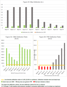
For deflection, all CMH Z-girts have a span-to-deflection ratio greater than the minimum of 90. The FRP girts had deflection ratios less than the minimum of 90 when subjected to a +40 PSF wind pressure and 5 PSF dead load.
In this case, generic FRP Z-girts failed to meet minimum design requirements for performance as supports for cladding and insulation in exterior wall application.
See the Appendix for further data.
Stresses for Case IV (24″ span, 16” spacing, 23″ cantilever) with CMH and Generic FRP
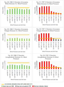
2 1/4″ through 4″ with positive wind pressure results in excessive deformation, so it is shown as a maximum
Deflection for Case IV (24” span, 16” spacing, 23″ cantilever) with CMH and Generic FRP
FEA Simulation Computer Images
The 3-D Solid Works 2020 package was used to model the different girts and run the FEA structural analysis simulations. Typical screenshots of the FEA analysis are shown in the figures below. The steel inserts are included in the CMH simulations but are hidden for clarity.
Figure 37: Typical FEA results output CMH model
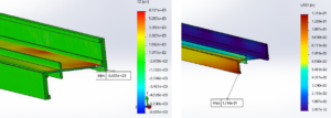
Figure 38: Typical cantilever condition at CMH ends
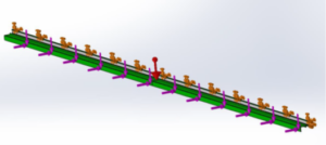
Figure 39: Typical FEA results output FRP model
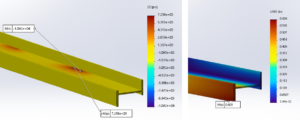
Figure 40: Typical FRP model with cantilever
Summary
In this study, a summary of engineering best practices was presented for composite metal hybrid Z-girts (GreenGirt CMH) and generic FRP sub-framing Z-girts with respect to the following areas:
- Best practices for structural stress analysis of Z-shaped girts as sub-frame members
- Best practice for detail for girt end conditions at the ends of individual girt pieces
- Best practices for attaching and connecting cladding to sub-framing composite Z-girts
- Best practices for using safety factors in the design of composite sub-framing Z-girts
Also, in this study, four standard wall configuration case studies illustrate the use of these best practices as well as the failure to use such best practices and the consequences in terms of the design being structurally unsafe and not meeting reasonable design criteria.
In all the FEA cases, the generic FRP Z-girts did not meet appropriate stress safety factors and/or deflection criteria.
In all the FEA cases, the composite metal hybrid Z-girts (GreenGirt CMH™) passed the structural loading conditions with appropriate stress, safety factors, and acceptable deflection.
Marketplace research has indicated generic FRP profiles with material properties called out in this study are commonplace. As illustrated in this study, such profiles do not provide an equivalent structural design when compared to CMH. The inability to take adequate safety factors, design criteria, and/or directional material properties under consideration may result in an unsafe design.
Appendix
Joinery Methods
Sub-framing Z-girts are usually manufactured in finite lengths (8 to 10 feet), which are often less than most wall lengths. Therefore, the end condition for the continuation of the Z-girts along the wall needs to be carefully detailed. Among the critical engineering metrics that need to be considered for these end conditions are:
- Structural stress and deformation analysis
- Attachment detail to substrate
- Allowance for thermal expansion along the length of the Z-girt
Typically, the only method of joining end conditions of generic FRP girts is to leave the girt ends cantilevered over the supports. Unless the stress and structural analysis is performed for such special end conditions (which often is not for generic FRP), such a condition is to be avoided.
Another method of joining the Z-girts is by lapping the Z-girt ends. Though this may be common practice with light gauge steel, it is not feasible with FRP Z-girts due to the relatively larger material thicknesses of FRP Z-girts. It also creates out-of-plane offsets in the wall’s vertical plane if the girts can be lapped at all.
The third method of joining Z-girt ends is butt joints on a substrate support such as a framing stud. Due to the required offsets for spacing of fasteners to the edge of the girt (minimum of 2.5x fastener diameter), a wider stud is required, as illustrated in Table 6, for a 16-gauge stud substrate.
Table 5: Required Offsets for Spacing of Fasteners to Edge of Girt
| Description | Required distance (inches) | |
| FRP Girt 1 | Edge of steel 3x thickness | 0.1875 |
| Edge distance of girt 2.5x fastener diameter (0.25) | 0.625 | |
| Fastener | 0.25 | |
| Space for thermal expansion | 0.08 | |
| FRP Girt 2 | Edge of steel 3x thickness | 0.1875 |
| Edge distance of girt 2.5x fastener diameter (0.25) | 0.625 | |
| Fastener | 0.25 | |
| Minimum required steel face | 2.205 | |
| Width of steel face (typical) | 1.5 | |
| Deficiency | -0.705 | |
From Table 5, the required distance to butt join the ends of two consecutive Z-girts on one stud exceeds the width of a typical single stud. This conclusion applies to steel stud substrates as well as wood stud substrates. Therefore, a wider stud or doubling the stud is required. Such a change is not often welcomed by owners or project managers due to the added costs involved. Therefore, butt-joining composite FRP girts on a single (or double stud substrate) is not best practice.
Another method of joining Z-girt ends is via properly engineered splices. However, for generic FRP Z-girts, such a splice detail is not available from any manufacturer in the market, is not utilized, and no manufacturer information or recommendations are available.
For best practices of properly engineering a splice detail, the following points need to be addressed:
- Properly designed splices need to allow for thermal expansion and transfer/resist all necessary loading.
- Splices should not be bulky as it can get in the way of rigid insulation.
- Splices should not be a single metal piece, as it will thermally conduct and create thermal.
- Splice connection should be through bolted.
The last method is the utilized method of joining CMH Z-girt ends. The method interlocks the ends of the girts using the steel inserts in the flanges, creating a solid, continuous connection. Such a connection allows for thermal expansion, transfers all necessary loads across the Z-girt, does not interfere with the insulation or wall plane, and does not require any additional components.
The CMH interlocking method of joining Z-girt ends is the best practice.
Cladding/Substrate Attachment Methods
Fiber Reinforced Polymer (FRP) Cladding Attachment
The conventional method to connect to FRP shapes is to use positive through connectors such as bolting and riveting with large enough washers to distribute stresses. Although this attachment method is effective in transferring loads, it can be expensive, labor intensive, and not practical for cladding attachment as it requires access to both sides of the wall to install a fastener.
From a practical perspective, the preferred method of connecting cladding to generic FRP Z-girts is using screws in a manner like the use of self-drilling screws with light gauge steel. However, the main shortcoming of using screws as an attachment method of cladding to FRP sub-framing members is that the load-carrying capacity is generally low and will not provide a reasonable safety factor against failure. A discussion of adequate safety factors and the rationale behind such requirements is presented in the following section. Furthermore, the load-carrying capacity of a screw in generic FRP can seriously degrade over time as the fastener loses its torque and pullout capacity due to the relaxation of FRP material.
Generally, introducing any fastener in the FRP materials in connections weakens the material compared to the main FRP part without fasteners. Therefore, using screws to attach cladding to FRP Z-girts is typically done for low levels of loading and is not considered a good practice due to the degradation of load-carrying capacity with time, especially when exposed to severe environmental conditions such as thermal cycling loads and freeze/thaw conditions.
An improvement on using simple screws for attaching cladding to generic FRP is using screws along with an adhesive. Such attachment methods usually provide better load transfer capacity and load retention levels compared to using screws’ low-level loadings, though such practice is not typically used in building wall structures.
CMH Thermally Broken Cladding Support Attachment
The best practice method is to attach cladding to CMH. Because CMH has a light gage insert as an integral part of the hybrid girt, self-drilling screws similar to what is used in light gage steel are driven, using common tools, through the FRP part of the girt and into the continuous steel insert, providing a positive base metal attachment capable of transferring high-level loads. Due to the combined effect of the FRP and the steel insert, the load capacity of such attachment is larger than the sum of the added component capacities (i.e., adding the load capacity of the FRP to the steel insert).
Most importantly, the CMH cladding connection retains its torque and pullout capacity over time and does not seriously degrade, even when exposed to harsh environmental conditions. Such performance is better, or at least similar to, the behavior of self-drilling screws in light gage steel.
Fiber Reinforced Polymer (FRP) Substrate Attachment
As far as connecting FRP Z-girts to the substrate structure, generic FRP girts require the use of sufficiently large washers to distribute the loads on the surface of the FRP flange and avoid possible fastener pull-through in the FRP material. Although the load transfer capacity may be sufficient, the FRP girt can be damaged from over-torque and is susceptible to stress singularities.
CMH Substrate Attachment
Attaching the CMH Z-girt to the substrate structure involves driving the screw fastener through the steel insert into the substrate with the FRP part of the girt sandwiched in between. This avoids the possibility of any pull-through from the FRP material, as the insert will resist such action.
Thus, connecting the CMH to the substrate has a superior load transfer capacity, eliminates stress singularities, and protects the composite from premature failures such as fastener pull-through.
Fastener Use with FRP Products
FRP joint connections are a delicate matter and must be done with great attention to detail.
The main reason for such complexity is that traditional connection methods used with classic materials such as metals do not work the same way or as well when joining to FRP structural shapes.
In general, the section of the FRP shape at the joint will be weaker than the main, undisturbed section away from the joint. For example, drilling a hole in composites reduces the load-carrying capacity. As some of the fibers become discontinuous, stress concentrations are created around the hole, which act as failure initiation and singularity points, and therefore the joint is weaker than the main part.
The following are weakening mechanisms that are introduced by driving a fastener into the FRP:1
- Singularity points for stress are created which weakens the section.
- Discontinuity in the fibers weakens the section.
- The discontinuity in the matrix is prone to crack propagation and fracture.
- Torque resistance of the screw into FRP deteriorates with time.
- Ability for load retention in case of fire is reduced.
A review of recommendations from FRP manufacturers with respect to connecting to their FRP structural shapes as indicated in their installation and design guidelines indicates the following conclusions:
Bolting
- FRP bolts, stainless-steel bolts, or galvanized bolts are recommended to connect FRP panels to FRP structural shapes.
- Bolt and Nut (Steel, Galvanized, Silicon, Bronze, Nylon, Polyester, etc.) methods are used to fasten FRP profiles together. It is best to use washers to distribute the loads.
- Threaded fiberglass rods with molded fiberglass nuts are used to fasten FRP profiles together. This is good for highly corrosive applications, and this method has good shear values.
- Using a bolt and threaded hole is a possible assembly technique for FRP to metal or FRP to FRP.
- Epoxies or other adhesives significantly improve joint strength.
- FRP bolts, nuts, and washers may be specified to suit aggressive environments or for electric isolation.
Riveting
- Tubular rivets can be used in conjunction with a washer or metal backup plate to connect FRP to FRP. They are stronger than pop rivets because of the solid shank, which requires accessibility from both profile sides.
- Solid rivets may be used to join FRP profiles together and should be used with backup plates or washers, but this method must have accessibility to both sides of the profile.
Using Screws (for Low Loading Demand)
Self-drilling screws can be used in applications involving mechanical connections when high-strength fasteners are not required.
Self-drilling screws may also be used in combination with adhesives.
- Lag screws can be used to attach FRP profiles to wood. A washer should be used to distribute the load. Lag screws are not recommended for fastening FRP to metal and are also not recommended for attaching FRP to FRP.
- Self-drilling screws work well in conjunction with adhesives. Screws may be used without adhesive but will not provide a high-strength connection (FRP to FRP).
Summary
Installing self-drilling screws into FRP as a joining method introduces numerous damage mechanisms, which make the load-carrying capacity deteriorate over time, create an unsafe design, and make the load-carrying capacity of the fastener unpredictable over time, deviating from the initial design intentions.
Safety Factors
In the allowable stress design method (ASD), safety factors compensate for uncertainties in quantifying design metrics (or variables) involved with FRP composite materials. Such variables are:
- Material properties such as strength and stiffness
- Uncertainties in loads and the modeling of the structure
- Service environment
In this context, the safety factor is defined as the ratio of the ultimate stress to the allowable stress. In this section, the different sources of uncertainty contributing to the safety factor for FRP component design will be summarized and quantified.
The nominal ultimate strength of the FRP material considered herein shall be based on a rigorous statistical approach of experimental data with a high confidence in the nominal value. The base value shall be denoted by R0, and all the safety factor components discussed below are to be applied to this base value.
The different constituents of a sound safety factor that can be used with the ASD method include:
- Material properties:
This factor accounts for the deviation of the actual strength of the FRP material from the actual nominal strength R0 and for the manner and consequence of the failure mode. Similar to other construction materials, a reduction factor of 0.8 is used, which corresponds to a safety factor multiplier of 1/0.8 = 1.25.
- Loads and modeling of the structure uncertainties:
Traditionally, dead loads are more predictable than live loads or transient loads such as wind loads. A load factor of 1.2 is commonly used with dead loads, and a factor of 1.4 is used with live loads. For cladding wall applications, since live loads are not applicable, a factor of 1.2 is appropriate.
- Service environment:
- Service temperature: The cavity of exterior walls of buildings where the FRP girts are typically located can reach a temperature as high as 190°F. Such high temperature warrants the use of a safety factor multiplier of 2 for a polyester-based FRP.2
- Moisture Effect: An assumption is made that the wall cavity remains dry, and therefore, the multiplier adopted is 1.
- Aging and UV effects: The FRP strength usually is affected by UV exposure. However, most well-designed FRP materials have UV inhibitor additives, which nullify such effects. Based on laboratory testing, a reduction factor of 10% in the strength may be expected in the long term, even though most sub-frame applications of girts are hidden in the cavity of the wall and not directly exposed to sunlight. A reduction factor in strength due to UV exposure of 0.9 is used, which can also be stated as a safety factor multiplier of 1.111.
- Notches and holes in the girt:
Any notches or holes in addition to the normal cladding or substrate fastener attachments are to be explicitly designed for and checked separately as a design item and are not included in the general safety factor values. The weakening of the material caused by the normal fastener attachment of cladding or to the substrate must be considered. For this purpose, a ¼” diameter fastener is assumed in a 1.5” to 2” wide section element of the FRP girt. The reduction factor in strength is proportional to the ratio of the hole-reduced section to the full section. For this, a stress factor multiplier of 1.2 is used.
- Creep effects:
Creep is a deformation condition of the material characterized by increasing deformation or strain under a constant sustained level of dead load stress. Glass fibers are relatively insensitive to creep; however, the polymer matrix creeps slightly. As a general rule, creep for FRP is not of significant concern if the sustained dead load stresses are limited below 20% of the maximum material stress.
For computing the minimum safety factor, the creep effects are considered insignificant. If creep effects are a concern, then design checks are to be made separately.
- Installation quality uncertainties:
Uncertainties related to the quality and workmanship of the installation are not usually included in the design safety factors. Situations such as missing fasteners, damaged girts, and poor site handling of the girts can be remedied by proper procedures and inspections. If such situations do happen, then it is considered as negligence and faulty workmanship or installation.
To summarize, a reasonable total safety factor can be estimated by multiplying the above factors, as summarized in Table 6. A minimum safety factor of 4 should be used for design.
Table 6: Safety Factor Multipliers and Cumulative Safety Factor
| Uncertainty | Safety Factor Multiplier |
| Material properties | 1.25 |
| Loads and modeling of the structure | 1.2 |
| Service temperature | 2 |
| Moisture effect | 1 |
| Aging and UV effects | 1.111 |
| Notches and holes in the girt | 1.2 |
| Creep effect | 1 |
| Installation quality effects | 1 |
| Cumulative Safety Factor | SF = 1.25*1.2*2*1*1.111*1.2*1*1*1 = 4 |
Depending on the specific project, the upper range of the safety factor can be as high as 6 or 8.
FEA Analysis Settings
- How to Accurately Run Composite Sub-Framing for Façade Cladding:
FEA analysis with 3D software packages, if performed correctly, is among the most accurate methods for analyzing FRP structural components used for cladding support. It is, at the least, highly recommended.
While both steel and composite can be used structurally within the building envelope, they must be analyzed differently when it comes to finite element analysis. Orthotropic analysis, point loading, stress concentrations, cantilevers, and other added complexities must be considered when performing structural analysis on composites. The following general guidelines are necessary to accurately structurally model components or systems of components.
- Orthotropic Analysis:
Unlike steel, composite properties like modulus of elasticity and tensile strength can vastly differ lengthwise and crosswise, which can lead to issues if not all directional properties are known or considered. An acceptable safety factor in the lengthwise direction must be duplicated in the crosswise direction as well. Finite element analysis should include the material properties in the x, y, and z directions for strength, modulus of elasticity, and any other properties that require consideration. Special care must be taken to ensure proper reference geometry is used so the correct material properties correspond to the correct direction.
Maximum stresses must be taken in every direction, with consideration taken to the allowable stresses in that direction. An acceptable safety factor of at least four for overall stress means nothing if the safety factor is two in the crosswise direction.
- Point Loading
Cladding options like stucco may result in uniform loading, but most claddings being used with composite sub-structures must utilize point loading to get the most accurate structural results. Point loads should be placed at a worst-case location, most likely midway between the attachments of the composite substructure to the substrate. This will result in worst-case stress concentrations, providing a more realistic model for what is occurring on the actual wall.
Also, some wall panel attachments are only around the outside perimeter of the panel shape and depending upon the size and shape of the specific panel, create unusually concentrated loads in some portions of the sub-framing. This must be noted beforehand, and worst-case conditions should be modeled. The modeler and professional engineer must be aware of this type of loading dynamic. This overlooked situation is most likely a trailing liability on a number of standard construction projects.
For example, an ACM panel may have a dead load of 3 PSF, but that panel will only attach along the perimeter. If the panel is 4′ x 12′, that is a 48 square foot panel that weighs 144 pounds. If the girt spacing is at 24” O.C., there will likely be 18 ACM clips to attach to the girts, with each carrying a +64 LB and -112 LB point load for wind to go with an 8 LB point load for weight. This is likely to result in an increase in stress and deflection over what would occur if uniform loading were utilized.
- Non-Bonded Contacts:
One of the important facets of finite element analysis is accurately reflecting what is happening in the model. Items like bonding in component contacts can result in a more rigid model than can realistically be expected. Whenever possible, use fasteners and make contact sets as realistic as possible to avoid making the model stronger than it would be on the wall.
- Mesh:
Performing FEA at a default mesh setting versus refining the mesh for a model can result in wildly different maximum stresses. It is recommended to use a curvature mesh, which results in the largest number of nodes and elements before reaching a point of diminishing returns.
When using fasteners in models, stress discontinuities can occur around fastener holes. Best judgment and practices should be used in discerning what is and is not of concern.
- Cantilevers:
In instances where butt joints cannot be used where composite substructures come together, the maximum cantilever between spans should be used to provide a worst-case scenario for stress. If the span is 16″, a cantilever of 15″ should be used, or if the span is 24″, a cantilever of 23″ should be used. This will provide a realistic design for what will occur when the composite substructure is being utilized on the wall.
- Fastener Placement:
In general, fastener spacing and edge distance in FRP composites are as follows:
- For center to center spacing of fasteners, at least 5 times the fastener diameter
- From edge of profile (along the profile), fasteners should not be placed closer than 2.5 times the fastener diameter
- From end of the profile, fasteners should not be placed closer than 3 times the fastener diameter
Final Checks
- Any FEA or calculations should be checked by the professional engineer doing the cladding assembly calculations. A Professional Engineer with knowledge of composites should sign off on the settings and results provided by the FEA. In summary, the FEA process for developing and using the FEA analysis need to include, as a minimum, the following items: The FEA model must be validated with respect to mesh size, loading model, and boundary support model. Such validation may be carried out by comparing simulation to actual representative experimental results. Also, such validation may be performed by comparing simulation results to known closed-formula types of solutions.
- Provide FEA to model and evaluate areas of the longest composite girt cantilever span possible between intermediate framing members/attachment.
- FEA shall include maximum dead load and wind load conditions.
- FEA shall include point loads representative of fastener locations.
- Maximum directional stresses in model shall have a safety factor of 4 or greater.
- Stresses shall be indicated and analyzed in three directions.
- FEA shall accurately replicate the wall system and physical loading dynamics.
- Report shall be furnished with the submittal.
- FEA shall be approved by a licensed PE familiar with composites.
- Butt joints (non-interlocking joints) of adjacent girts shall be installed on a minimum surface width of 3” or double stud condition to accommodate proper fastener margins to composite.
Structural Analysis – Durability and Testing
FRP structural components need to be tested for the durability of the structural strength and stiffness to assess the environmental exposure effects during their service life.
Depending on the use of a building, the service life of a building varies from 5 years for temporary structures to 100 years for monumental structures. Fifty years is the usual design service life for a normal-use building such as a commercial or institutional building.
The maximum recommended service temperature of pultruded FRP components is 40°F below the glass transition temperature, Tg, of the composite system. The glass transition temperature of the composite system is the temperature above which the matrix changes from glassy to rubbery state and the mechanical properties degrade.
Among the environmental effects that FRP components may be sensitive to and need to be tested for are the following:
- Moisture (weather exposure)
- Temperature (weather exposure)
- Sun ultraviolet light exposure (if conditions of use allow for such exposure)
- Chemical attack (if conditions of use allow for such exposure)
- Salt exposure
Among the ASTM standards that are used to test for the above environmental effects are the following:
- For accelerated weathering effects (moisture, temperature, ultraviolet, etc.):
- ASTM G152 “Standard Practice for Operating Open Flame Carbon Arc Light Apparatus for Exposure of Nonmetallic Materials”
- ASTM G155 “Standard Practice for Operating Xenon Arc Light Apparatus for Exposure of Non-Metallic Materials”
- For Freeze-Thaw evaluation, a testing procedure like ASTM C666 “Standard Test Method for Resistance of Concrete to Rapid Freezing and Thawing,” may be adopted.
- Salt spray resistance
- ASTM B117 “Standard Practice for Operating Salt Spray (Fog) Apparatus”
- Water resistance
- ASTM D2247 “Standard Practice for Testing Water Resistance of Coatings in 100% Relative Humidity”
Further discussions of durability and failure modes will occur in a future paper.
Results and Discussion
The following section presents a performance comparison between generic FRP components and hybrid metal composite components as used for insulation and cladding supports in exterior walls of building envelopes. Both materials are glass-fiber-based FRPs.
The performances of the two materials are evaluated using FEA stress analysis with respect to maximum stresses, safety factors, and maximum deformations, as the material is subject to loadings representative of field conditions.
The FEA stress analysis shows the superior performance of the CMH compared to the generic FRP, even though the generic FRP girt has a thicker section of FRP than the CMH girt. The generic FRP flange is 1.85 times thicker than the CMH flange, while the generic FRP web is 1.5 times thicker than the CMH web. Both sections support the same insulation thicknesses and, therefore, have similar depths.
Notes/Disclaimers
The content of this study is for general information purposes only and does not constitute legal, engineering, accounting, regulatory, or tax advice.
The material presented herein was prepared with great care and in accordance with industry recognized engineering principles and practices.
This information should not be used for any specific project without consulting with qualified engineering professionals in the area where the project is located, as design criteria are specific to each project. Furthermore, laws and regulations are specific to each location.
The reference to generic FRP girts is a general term and does refer to or imply any specific product brand name or manufactured or specific marketed product. Any resemblance in naming, description, dimensions, or configuration is merely a coincidence.
GreenGirt CMH™ is a registered Trademark for Advanced Architectural Products (A2P).
The user of the content of this study assumes all risks and liabilities associated with such use.
A2P does not make warranty or representation of any kind with respect to accuracy, completeness, or suitability of use for any specific project of the information contained in this study.
A2P does not assume and specifically disclaims any liability from the use of the information contained in this study.
The information in this study does not constitute or imply suitability of any product for any specific project and does not imply any warranty of performance of any product for any specific project.
Due to the general nature of the information contained in this white paper, such content cannot be used or referenced in any legal document such as construction documents, specifications, drawings, contracts, and codes.
Properties used for simulations were based upon data publicly available from manufacturers or using industry standard data to bridge the gap where information was missing.
This study is intended, but not promised or guaranteed to be, current, complete, or up to date. A2P may update the study as more data becomes available.
All FEA was done with SOLIDWORKS Simulation Software.
Wind loads utilized are ultimate per ASCE 7-10.
While Table 1604.3 of the International Building Code gives a minimum of L/120 for deflection limits, footnote A provides L/90 for secondary wall members supporting formed metal siding.
The content of this study excludes thermal spacers and only refers to zee shapes.
This study does not guarantee the performance of any specific products, including but not limited to GreenGirt CMH.
Engineering data in this study is meant to be used as an aid and does not constitute stamped engineering calculations.
Engineering data for GreenGirt CMH is based on installation per A2P installation guides.
Engineering data does not include the performance of the substrate or cladding. Substrate is assumed to be strong enough to carry the GreenGirt CMH or Generic FRP.
The purpose of this study is to provide basic information to product users for use in evaluating, processing, and troubleshooting the use of certain composite products. The information provided is general or summary in nature and is offered to assist the user. The information is not intended to replace the user’s careful consideration of the unique circumstances and conditions involved in the use and processing of composite products. The user is responsible for determining whether this information is suitable and appropriate for the user’s particular use and intended application.
Technical Information: Technical information, recommendations, and other statements contained in this document or provided by A2P personnel are based on tests or experience that A2P believes are reliable, but the accuracy or completeness of such information is not guaranteed. Such information is intended for persons with knowledge and technical skills sufficient to assess and apply their own informed judgment to the information. No license under any A2P or third-party intellectual property rights is granted or implied with this information.
Patents: See GreenGirt.com/patents/
References:
- Krause, G. Matt; Gauchel, James; and Aouadi, Fadhel. “Use of high performance Composite Metal Hybrid (CMH) for NFPA 285 fire-rated continuous insulations systems.” July 25, 2016*
- “Structural Plastic Design Manual,” American Society of Civil Engineers. ASCE Manuals Reports on Engineering Practice No 63, ASCE 1984.
- “Pre-Standard for Load and Resistance Factor Design (LRFD) for Pultruded Fiber Reinforced Polymer (FRP) Structure,” American Society of Civil Engineers. November 2010
- Flynn, Susan Keen, and O’Leary, Melissa. “University R&D Advances Novel Ideas to Ground-Breaking Applications,” American Composites Manufacturers Association, Susan Keen Flynn and Melissa O’Leary, “Composites Manufacturing,” July/August 2017, Pages 14-16
- Thomas, Sabu et. Al., “Polymer Composites – Vol. 1,” Wiley-VCH 2007
- Bank, Lawrence C. “Composites for Construction,” John Wiley & Sons, 2006
- “Guidelines and Recommended Practices for Fiber-Reinforced-Polymer (FRP) Architectural Products,” ACMA: American Composites Manufacturers Associations. 2016.
- Duthinh, Dat. “Connection of Fiber Reinforced Polymer (FRP) Structural Members: A Review of the State of the Art,” National Institute of Standards and Technology 6532, August 2000.
- “Prospect for New Guidance in The Design Of FRP,” European Commission, 2016
- “Minimum Design Loads for Buildings and Other Structures (ASCE Standard 7-10),” American Society of Civil Engineers. 2010, Reston, VA.
- “International Building Code,” International Code Council, 2015. Falls Church, VA.
- Aldrich, Robb A., Arena, Lois, and Zoeller, William. “Practical Residential Wall Systems: R-30 and Beyond,” Steven Winter Associates Inc.
- Winandy, Jerrold E., and Beaumont, Rhett. “Roof Temperatures in Simulated Attics,” United States Department of Agriculture Forest Service
- Maurenchrecher, A.H.P., and Chidiac, S.E. “Temperature Measurements on Brick Veneer,” National Research Council Canada
*Title of paper changed to reflect current product nomenclature
Download Now: Best Practice: Structural Engineering for Composite Substructure Materials – Composite Metal Hybrid (CMH) vs. Generic FRP for Cladding Support of Exterior Walls’ Engineering Study
© 2020 Advanced Architectural Products. All rights reserved.