
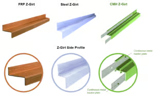
Types of “Z-Girt” Sub-Framing Material

Z-girts and fasteners play crucial roles within the building envelope: Z-girts serve as attachment points for cladding, assist in establishing thermal breaks, and ensure a level surface for cladding installation, while fasteners maintain structural integrity by anchoring the Z-girt in place. This sub-framing is expected to withstand the rigors of long-term load-bearing and the fluctuations in building envelope temperatures. A cohesive selection of Z-girt material and fastener type is therefore essential for guaranteeing the long-term reliability of the structure.
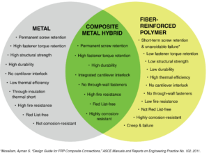
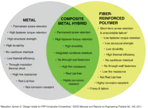
Three materials were tested, selected for their relevance in contemporary construction practices and the value of their comparative analysis.
-
Fiber-Reinforced Polymer (FRP)
- A versatile thermoset plastic well-suited for use in both new construction and repair applications. As a composite integrating fibrous materials within a polymer matrix, FRP addresses many of the drawbacks of materials like wood, steel, concrete, and masonry (1) through its high strength-to-weight ratio, corrosion-resistance, cost-effectiveness, and thermal insulative properties.
-
Steel
- Steel, with its established robustness, serves as a benchmark for structural integrity and durability that all sub-framing materials should aim to match or surpass to ensure safety and long-term performance. It is a common material with high load-bearing capacity at the cost of susceptibility to corrosion and high thermal conductivity, leading to potential thermal bridging. It offers screw pull-out resistance due to its tensile strength and inherent ductility.
-
CMH™
- A high-performance composite metal hybrid building material, such as GreenGirt CMH Z-girts, combines the corrosion-resistant and insulative properties of FRP. It also incorporates the structural resilience provided by a continuous metal component. Its unique composite ensures robust screw retention. This allows screws to be used directly, tapping into a continuous metallic structural support for effective and reliable load distribution.
The recommendations provided in the conclusion are straightforward and grounded in empirical data. Our goal is to furnish stakeholders with actionable insights. These insights aim to enhance the longevity of FRP constructions. They also identify and mitigate potential liabilities, ensuring safer, more durable, and responsible building practices.
We will discuss why, in structural or semi-structural applications, a self-drilling screw anchored into an FRP substrate is a short-term connection, whereas a metal-to-metal connection using steel or CMH is the best long-term fastening solution.
FRP Fundamentals
The history of FRP in structural applications dates to the early 20th century. Initially, FRP gained attention for its use in aerospace and marine engineering, and by the 1960s and 1970s found its way into civil construction. (2) When used correctly, FRP is regarded as a reliable structural material that offers a versatile alternative to traditional construction materials like steel and concrete.
FRP can be created in various ways, including a process called pultrusion. Invented in 1959 (3) by W. Brandt Goldsworthy, the pultrusion machine converts continuous lengths of reinforced fibers and liquid resin into a fiber-reinforced plastic using a heated forming die. The fibers, which can be glass, carbon, or aramid, provide the material with its mechanical strength. The polymer matrix, illustrated here as two distinct layers for clarity, infuses throughout the glass fibers and acts as the “glue” binding them together. This infusion evenly distributes stress along the composite and imparts shape to the material.
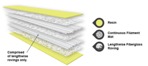
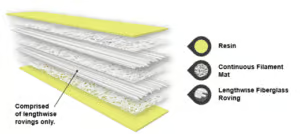
Figure 1: Depiction of the layers within a generic FRP composite. Note that the resin will saturate the assembly in its entirety.
Two of the primary fibers used in pultrusion are the continuous filament mat and fiberglass roving. The continuous filament mat consists of randomly oriented molten glass fiber strands, and the roving is a fiberglass strand that has been repeatedly doubled back on itself lengthwise. Typically, rovings comprise the bulk of reinforcement, conferring increased lengthwise strength and stiffness.
Factors Affecting Durability: Service Temperatures and Connection Details
Service Temperatures
We all know that getting to a car left parked in the sun on a hot summer’s day can feel like climbing into an oven. Vehicles parked outdoors in the sun, with ambient temperatures between 72 – 99°F (22 – 37°C), have been found (4) to reach interior ambient temperatures of 196°F (91°C ) after just 1-2 hours in the sun. Moreover, surface temperatures surpassed even the interior air temperatures, with dark dashboards registering temperatures over 220°F (104°C). Cars have been found to have similar heat gain to that of a building envelope.
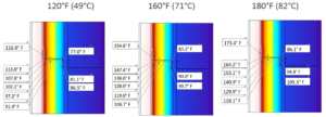
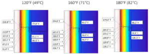
The building envelope, which serves as the protective barrier of a structure against external elements, operates within a service temperature range of -40°F to 180°F.² (6) This system can undergo significant heat gain or buildup and includes diverse materials across the exterior wall assembly — from sheathing and waterproofing to exterior insulation, sub-framing, and cladding. A key observation is that building envelope service temperatures can surpass ambient temperatures by up to 90°F. This can be a concern, particularly if FRP profile manufacturers haven’t tailored their products for elevated temperatures, as FRP typically considers only ambient temperatures in its design.
² ASHRAE and IECC provide temperature ranges that are generally accepted and designed for: 55 to 85 degrees Fahrenheit for interior building components (7) and -40 to 120 degrees Fahrenheit for exterior ambient temperatures (8)
It’s also important to note that a considerable amount of sub-framing sits within the building envelope. This placement means it experiences extensive temperature fluctuations in the -40°F to 180°F range. This underscores the importance of choosing materials robust enough to handle these variations in the long term.
Connection Details
A crucial element of sub-framing integrity is how it connects. When using generic FRP, best practice calls for using backer plates along with bolt or screw assemblies. Established guidelines, such as those from the ASCE (9), have codified best practices for over 50 years. They emphasize the importance and methodology of these connection details, validated over time. There are several technical advantages to these established practices:
- Laminate Compression
- These methods effectively compress the drilled hole, ensuring that the laminate layers bind securely. This not only strengthens the connection point but also enhances the overall stability of the structure.
- Force Distribution
- Incorporating backer plates and bolt/screw assemblies distributes the force uniformly over a larger tributary area. This approach surpasses what a hole alone would achieve. This broader distribution, often referred to as the “X” area, minimizes localized stress points, further reinforcing the connection.
- Stress Redirection
- One of the notable features of this connection method is its ability to redirect stresses. Instead of concentrating the stresses in the potentially weaker interlaminar zones, the stresses shift. They move to the stronger longitudinal and transverse directions of the laminate. This redirection not only optimizes the load-bearing capacity and the connection but also prolongs its lifespan.
These connection methodologies are not just theoretical best practices; they have undergone 50 years of proof and refinement. Furthermore, GreenGirt CMH inherently aligns with these best practices owing to the continuous backer plate integrated into its design. This not only enhances its strength but also automatically facilitates the compression, distribution, and redirection of forces.
Joining FRP with screws or bolts comes with special engineering considerations:
- Use a backer plate for hole drilling to minimize backside delamination damage or “hole push-out.”
- Install bolts and/or screws with washers to backer plates to distribute the fastener load.
- Utilize established ASCE best practices to minimize the risk of screw pull-out and ensure structural integrity.
GreenGirt CMH design accounts for these established engineering guidelines for joining FRP:
- The continuous steel backer plate on the cladding side flange acts as a hole-drilling backup plate. The self-drilling fastener first drills through the cladding, then the FRP, and finally through the steel backer plate. Self-tapping threads bite first into the steel insert, guiding the screw through the FRP.
- The installed cladding attachment screw connects structurally to the continuous steel backer plate. It is part of a lattice-like network of steel inserts that distribute tributary loads.
- The backer plate on the substrate side flange for CMH protects against pull-over/pull-through of fasteners when going through FRP.
Short-Term Connections: Sheet Metal Screw to FRP Substrate
Why isn’t a screw without a backer plate compatible with the material properties of FRP? We’ll explain the chain of events.
1. Sheet Metal Screws Anchored Directly into FRP: Damaging the Composite Structure and Matrix
Among the common fastening methods — nails, screws, bolts, and adhesive — self-drilling or self-tapping screws have become a standard in building construction, although their successful use largely depends on the materials they’re drilling and fastening into. Self-drilling fastener manufacturers design their products primarily for metal and wood applications, and provide guidelines based on their materials.
Utilizing self-drilling/tapping screws based on misapplied guidelines leads to significant drawbacks – namely, that the structure loses integrity the moment that the screw enters the FRP. The issue arises from the incompatibility between the design intent of standard screw threads and the anisotropic mechanical behavior of FRP materials. The thread design of the fastener, geared for biting into metal, disrupts the fibers that give FRP its strength. Finite Element Analysis (FEA) reveals that these localized stresses can result in the initiation and propagation of cracks, especially if the composite has any pre-existing imperfections. (10) This drastically reduces the composite’s strength against fatigue and its long-term performance. (11)
These issues are summarized by Dr. Mahmood Haq, Civil & Structural engineering professor at Michigan State University: “Drilling a hole in composites sacrifices up to 60 percent of the load carrying capacity. The minute you drill a hole, the fibers become discontinuous, you create stress concentrations around the hole, and you cause delamination, all of which act as failure initiation points, thereby weakening the resulting joints.” (12)
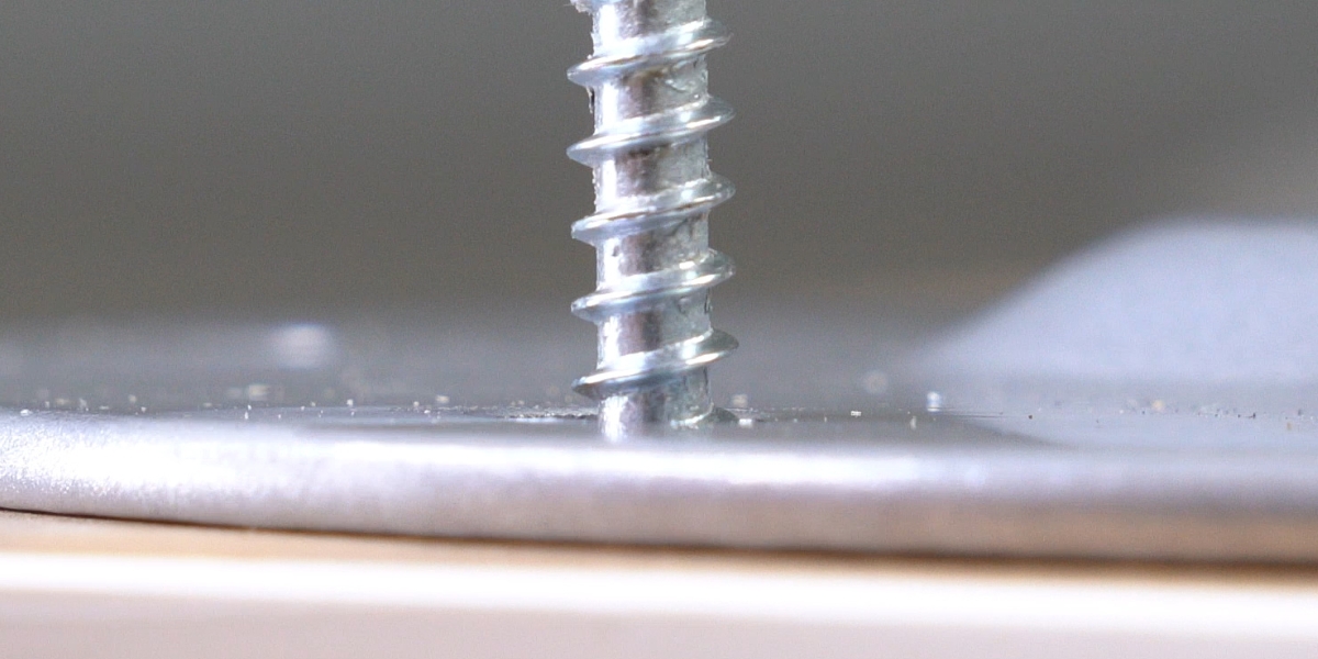
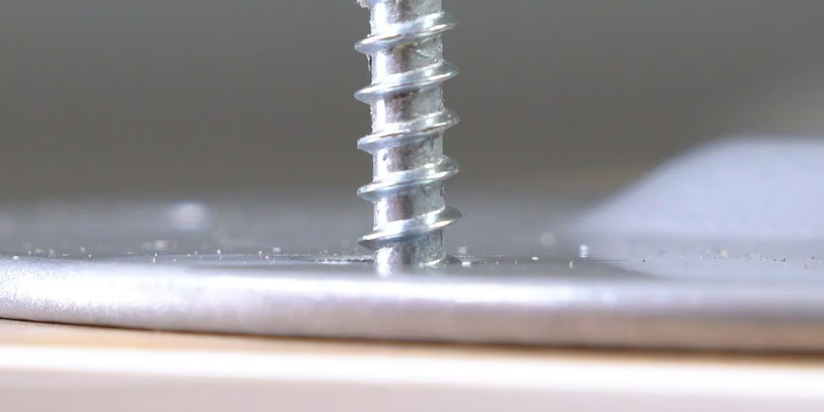
2. Sheet Metal Screws Anchored Directly into FRP: Creating Force Concentrations
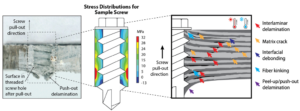
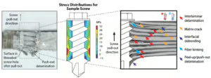
The introduction of a screw creates a significant force concentration. Low-to-medium stress in a broad tributary area of the composite concentrates into a much weaker interlaminar zone of the composite.
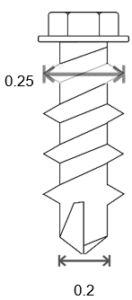
Let’s look at a real-life example. A typical fastener attaches cladding every 24 inches horizontally and vertically, covering a 4-square-foot area (or 576 square inches) per fastener. Now, if wind applies a pressure of 20 pounds on every square foot of this area, each fastener will need to handle a load of 80 pounds. Usually, a backer plate helps manage this by spreading out the load.
However, when fastening into a material like FRP, things change. Figure 3 shows that most of the stress from the load focuses on a small area around the screw. You can find the area bearing this stress per thread, therefore, using the following formula:

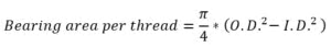
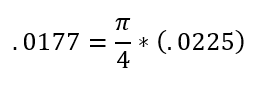
For the specific type of screw used in this example, this stress-bearing area per thread is about 0.0177 square inches. The 576 square inches of wind pressure concentrate on a small area around the screw. This increases the force on the screw by 8,000 to 30,000 times, depending on the number of screw threads examined. This demonstrates how the material and fastening method impact stress on a small area. This factor is crucial for ensuring the structure’s safety and durability.

This force concentration has severe implications. Even a fastener without any applied external load can exert an interlaminar force of up to 4,641 psi on the FRP. To put this in perspective, the overall interlaminar capacity of many FRPs ranges between 2,000 to 6,000 psi. This means that the fastener is already pushing the material to its limits, and with the addition of any external loads, the risk of failure increases substantially. Furthermore, the strength capacity of the screw thread will start to decline immediately due to the phenomenon known as screw creep. The preload applied to the fastener during installation can further exacerbate this situation, intensifying the interlaminar stresses and potentially accelerating the onset of failure.
3. Sheet Metal Screws Anchored Directly into FRP: Declining Screw Capacity Due to Elevated Service Temperatures
Building envelope service temperatures (a) have been shown (14) to reach temperatures higher than 176° F even in the mild climates of North America due to a variety of factors (15). When screws are used in hole-damaged composites, they act as conduits for these exterior elements, channeling them directly into the compromised laminate. This can cause thermal stresses due to the differing expansion and contraction rates between the metal screws and the composite material.
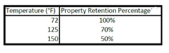
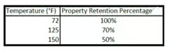
Such temperature-induced stresses, combined with moisture ingress around the screw holes, further heighten the risk of delamination and degradation of the composite (16). Over cycles of changing weather conditions, this direct conduction exacerbates progressive damage accumulation. Service temperatures within a building can surpass the design temperature thresholds for screw capacity in both polyester and vinylester resins. At these elevated temperatures, the capacity can diminish by more than 90%, severely compromising the integrity and performance of the connection. (17)
4. Sheet Metal Screws Anchored Directly into FRP: Understanding the Impact of Screw Creep and Its Gradual Deformation
Creep is a material’s time-dependent deformation under load. It is a continuous, progressive process; the creep rate is dependent on factors such as temperature and applied stress (10). This phenomenon emerges primarily due to the high-stress concentrations experienced at the interface between the fastener threads and the interlaminar regions of the material. As the name suggests, screw creep pertains to the gradual deformation of the screw under sustained loads, especially in areas of concentrated stress. Over time, this can lead to a reduced holding capacity and potential failure of the connection.


Detailed power law calculations further elucidate the mechanics of this process. While an isotropic material like steel only experiences creep at high temperatures beyond its service temperature, FRP is not so simple: creep in FRP follows a known Power Law relationship representing the relationship between stress ratio and time to failure. This lifespan calculation permits the prediction of the fatigue life of FRP laminates. (19) This power-law-driven accumulated damage reduces the fastener’s effectiveness over time, making the connection increasingly vulnerable.
Due to FRP’s heterogeneous fiber distribution, there is tremendous material property variation within the area of the composite and domain area of the screw. In statistical modeling of physical phenomena like screw-holding power or creep-rupture, homoscedastic data is preferred. However, tests on Glass Fiber-Reinforced Polymer (GFRP) samples showed inconsistent variability, known as heteroskedasticity, in screw fastener pull-out at certain temperatures.
In simpler terms, heteroskedasticity refers to the phenomenon where the dispersion or spread of a particular measure, such as the screw fastener pull-out strength, is not constant across different levels of another variable, like temperature. Ideally, for a consistent model, we would expect the variability to remain the same across all temperatures — this consistency is termed homoskedasticity. But with GFRP, as temperature changes, the variability in the pull-out strength also changes unpredictably.
This inconsistency is attributed to localized variations in FRP’s physical properties, especially within small areas like screw-holes. Such micro-variations are less problematic in larger load-transfer areas, where deviations average out.
5. Sheet Metal Screws Anchored Directly into FRP: Facing the Long-Term Consequences of Accumulated Damage
Each engagement of the fastener with the composite material, be it during the initial installation or during load adjustments, inflicts micro-damages on the composite. (20) Over time, these micro-damages accumulate, progressively compromising the fastener’s retention within the composite material. The term “screw creep” captures the gradual, yet persistent, loosening of the fastener from its anchored position within the FRP, exacerbated with each load cycle the connection undergoes.
Moreover, the scenario of preloading the fastener, a common practice aimed at ensuring tight connections, inadvertently magnifies the rate of damage accumulation. The additional stress factor compounds the ongoing damage accumulation and ultimately accelerates fastener retention failure. This undermines the longevity and reliability of the fastener-composite connection, with repercussions extending to the overall structural integrity. Diminished fastener retention directly translates to a weakened connection, increasingly jeopardizing the structural cohesion as time goes on.
Summarizing Fastener Attachment for Cladding in Real-Life Applications: FRP vs. Steel/CMH
Fasteners attached to Fiber-Reinforced Polymer (FRP) behave differently than those anchored into steel. One key difference is that FRP deteriorates over time due to factors like temperature and load, while steel remains stable.
Let’s review an example of these concepts.
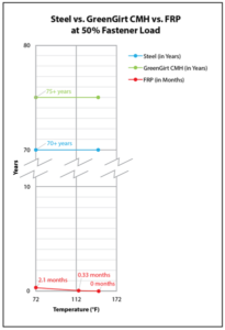
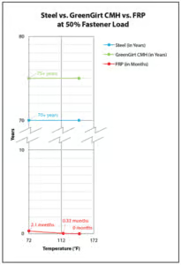
In steel, a self-drilling fastener operating at 90% of its capacity can last for decades, assuming no corrosion/ancillary factors. This stability over time, service load, and temperature is a well-accepted assumption in the construction industry.
In contrast, a self-drilling fastener in FRP at 90% capacity usually lasts only minutes or hours at room temperature. Higher temperatures further accelerate FRP’s decline.
Additionally, these figures don’t account for real-world construction challenges. The rate of defective or improperly installed self-drilling screws can range from 3% to 5%. In a 20,000-square-foot wall area with cladding fasteners spaced at 16″ x 24″ on center, 7,518 fasteners would be used. If 4% are defective, that equates to 300 fasteners that are no longer functional for cladding attachment.
Assuming a fastener safety factor of 3, or a 33% maximum load, fasteners adjacent to the defective ones could experience a doubled load, reaching 66% of their capacity. Under these conditions, at a consistent load, the lifespan of these fasteners would be measured in hours, not years.
In such a project, there would be 300 potential locations where this could occur, putting the cladding installation at risk of cascading failure.
It’s worth noting that actual job site conditions, such as wind and temperature, can significantly affect the rate of fastener failure in FRP installations. These variations will make the eventual fastener failures more unpredictable.
Test Methods
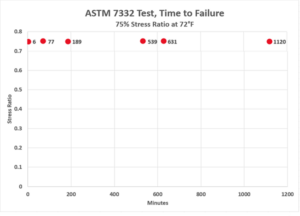
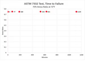
Given the vulnerability of FRP to screw-creep under time and elevated temperatures, we conducted testing to determine baseline fastener retention performance. Our testing regimen incorporated the variables of time, force, and heat to provide a realistic demonstration of the conditions that FRP encounters in real-world applications. We aimed to capture reliable, actionable data about the screw retention value of FRP over time under sustained elevated temperatures.
The ASTM D7332-B was used as a starting point for the testing. ASTM D7332-B is an approved method utilized to measure the fastener pull-through resistance of FRP composites, particularly those reinforced by high-modulus fibers. It evaluates the force-versus-displacement response when a mechanical fastener is pulled through a composite plate. It is important for this test to be run under a load, taking into account time and service temperature.
Our tests demonstrated the scenario wherein a building envelope functions at the upper limits of its service temperature range over a seven-day period. By quantifying the interplay of force, time, and temperature on FRP performance and evaluating screw pull-out resistance under these conditions, we aimed to evaluate the structural integrity and durability of FRP materials within such operational parameters.
The outcomes of the test reveal significant insights into the fastener retention capabilities of various brands of FRP, as well as the comparative capabilities of steel and GreenGirt CMH™.
Discussion
The detailed test results provide valuable insights into the performance of different materials under specific conditions. When examined under a temperature of 180°F (82°C) with a #14 T3 fastener at 50% of an FRP ultimate pull-out load, Generic FRP A failed almost immediately, at 59 seconds, with a test value of 435 LB. This contrasts with Generic FRP C, which lasted for over 2 hours but eventually also failed at the same test value and conditions. Generic FRP B was slightly more durable at a lower temperature of 158°F (70°C), lasting 1 minute and 24 seconds before failing.
This data clearly illustrates the inconsistent performance among different batches of generic FRP, even when tested under identical conditions. The failure within such a short span of time suggests a lack of suitability for applications requiring long-term reliability, especially at elevated temperatures. There is a noticeable range of performance within the same batch of FRP, in addition to performance variation across different manufacturers.
The 16-gauge steel and GreenGirt CMH – the standard GreenGirt CMH product line with a 16-gauge steel G-90 insert – demonstrated higher resilience. Both were tested at 180°F (82°C) with a #14 T3 fastener at 90% of a typical ultimate pull-out value, which corresponds to 552 lbs. Neither material failed after seven days of continuous testing. This highlights the exceptional durability, consistency, and suitability of these materials for structural applications requiring high pullout strength, even at elevated temperatures.
It is also noteworthy that the 16-gauge steel and GreenGirt CMH were tested at a higher percentage of an ultimate pull-out value (90%) compared to the FRP samples (50%) and still did not fail. This not only validates their inherent material advantages but also demonstrates that they can be relied upon for longer periods, even under more demanding conditions.
To summarize, the test results indicate a significant performance gap between CMH and 16-gauge steel as compared to various types of generic FRP, particularly in terms of screw pull-out strength and durability. Furthermore, the wide variations in the performance of different FRP types highlight the need for careful selection and quality assurance when opting for these materials.
Recommendations
In light of new findings and best practices, the following revised recommendations are offered for fastening solutions in FRP-based constructions:
- Using GreenGirt CMH ensures thermally efficient and secure fastening without the need for additional support mechanisms. Utilizing standard sheet metal screws is sufficient with CMH, as it has been proven to provide a reliable grip for fasteners where generic FRP failed. Using CMH ensures both sustainability and structural security, as its design automatically aligns with industry best practices.
- Using generic FRP necessitates the use of a metal backer plate at the fastening point. Whether fastening with a screw or bolt, a metal backer plate is essential to distributing the stress and significantly reducing the risk of fastener pull-out, a challenge distinct to generic FRP applications. This straightforward measure is critical in enhancing the fastening security of FRP materials.
- Using generic FRP necessitates a 7-day ASTM D7332-B pull-out test conducted at a minimum temperature of 180°F to verify material durability. Generic FRP is an inherently variable material. This test is crucial to ensuring the durability of the FRP in use. Utilize a minimum of ten samples to acquire a statistically significant dataset, thereby validating the fastener’s reliability in such materials.
Implementing these recommendations ensures that both the material quality and safety of FRP-framed or -sub-framed structures. Failure to adhere to these guidelines could compromise your building’s structural integrity. By following these proactive measures and best practices, rooted in empirical findings and a deeper understanding of material properties, you can reduce trailing liabilities and propel the construction sector toward a more resilient future.
Download the full article here.
Get Specs & Details for Continuous Insulation Systems with Permanent Fastener Connections
Download system-specific resources to support you in specifying continuous insulation systems with reliable, permanent fastener retention.
Download A2P’s Technical Resources
Have additional questions about fasteners? Our expert engineers are available to support you.
Talk with A2P’s Engineering Experts
Related Resources:
View “Best Practice: Fastener Retention”
A2P’s Continuous Insulation Z-Girt Product Selector Tool
Unavoidable Failure in FRP-Only Fastener Connections
Gary M. Krause, President/CEO and Director of Engineering
Matthew Krause, Materials & Process Engineer
Sean Walsh, Chemical Engineer/Materials & Process Engineer
Zach Kukkonen, Civil Engineer
Sources:
- Jawed Q. Fibre-Reinforced Polymer (FRP) in Civil Engineering. Next Generation Fiber-Reinforced Composites – New Insights. 2023 Mar.
- Wilson BC. Pultrusion. In: Peters ST, editor. Handbook of Composites. Springer New York, NY; 1998. p. 488–524.
- Sims M. What is Pultrusion? The History of Pultrusion. [Internet]. Pultrex. 2015 [cited 2023 Oct 10]. Available from: https://pultrex.com/the-history-of-pultrusion/
- Null J. Heatstroke deaths of children in vehicles. San Francisco (CA): Department of Geosciences, San Francisco State University; 2010.
- A2P1072: Building Envelope Components: Examining Service Lives and Lifespans [Internet]. Advanced Architectural Products. 2023. Available from: https://GreenGirt.com/building-envelope-components-examining-service-lives-and-lifespans/
- A2P1069: Maximum Service Temperature of Traditional Building Materials: A Comprehensive Overview [Internet]. Advanced Architectural Products. 2023. Available from: https://GreenGirt.com/a2p1069-maximum-service-temperature-of-traditional-building-materials-a-comprehensive-overview/
- National Institute of Building Sciences. “Building Envelope Design Guide – Introduction.” Whole Building Design Guide. Accessed October 24, 2023. https://wbdg.org/guides-specifications/building-envelope-design-guide/building-envelope-design-guide-introduction.
- ANSI/ASHRAE Standard 55-2017 Thermal Environmental Conditions for Human Occupancy. 2017.
- International Code Council. International Energy Conservation Code. Chapter 3 CE General Requirements, Table R301.1. Accessed October 24, 2023. https://codes.iccsafe.org/content/IECC2018P4/chapter-3-ce-general-requirements.
- Structural Engineering Institute. Minimum Design Loads for Buildings And Other Structures. 1801 Alexander Bell Drive Reston, Virginia 20191: American Society of Civil Engineers; 2010.
- Ashby MF, Jones DRH. Engineering Materials 1. 5th ed. The Boulevard Langford Lane, Kidlington, Oxford OX5 1GB, United Kingdom: Elsevier Ltd.; 2019.
- Galińska A. Mechanical Joining of Fibre Reinforced Polymer Composites to Metals—A Review. Part I: Bolted Joining. Polymers. 2020 Sep 30;12(10):2252.
- Khashaba, U.A.; El-Sonbaty, I.A.; Selmy, A.I.; Megahed, A.A. Machinability Analysis in Drilling WovenGFR/epoxy Composites: Part I—Effect of Machining Parameters. Composites Part A Appl. Sci. Manuf. 2010, 41, 391–400.
- Nakatani H, Hatanaka Y. Process-induced damage and its effect on strength of composite – aluminum alloy joint by FDS technique. Mechanical Engineering Journal. 2023;10(4):23-0006923-00069.
- Government of Canada NRCC. CBD-47. Extreme Temperatures at the Outer Surfaces of Buildings – NRC-IRC [Internet]. web.mit.edu. 1963. Available from: https://web.mit.edu/parmstr/Public/NRCan/CanBldgDigests/cbd047_e.html
- Bishara A, Kramberger-Kaplan H, Ptatschek V. Influence of different pigments on the facade surface temperatures. Energy Procedia [Internet]. 2017 Oct;132(132):447–53. Available from: https://doi.org/10.1016/j.egypro.2017.09.662
- A2P1070: Service Temperatures: Exploring Building Science Fundamentals [Internet]. Advanced Architectural Products. 2023. Available from: https://GreenGirt.com/service-temperature-exploring-building-science-fundamentals/
- Rosa IC, Morgado T, Correia JH, Firmo JP, Silvestre N. Shear Behavior of GFRP Composite Materials at Elevated Temperature. Journal of Composites for Construction. 2018 Jun 1;22(3).
- Banks L, Ellingwood B, GangaRao H, Zureick AH, Lopez-Anido R, Mottram JT. Pre-Standard for Load & Resistance Factor Design (LRFD) of Pultruded Fiber Reinforced Polymer (FRP) Structures. American Society of Civil Engineers; 2010.
- Adam T, Dickson RF, Jones CR, Reiter H, Harris BT. A Power Law Fatigue Damage Model for Fibre-Reinforced Plastic Laminates. Proceedings of the Institution of Mechanical Engineers, Part C: Journal of Mechanical Engineering Science. 1986 May 1;200(3):155–66.
- Banks L, Cai Z, Qiu C, Bai Y, Zhao XL. Pullout Behavior of Connections Using Self-Drilling Screws for Pultruded Fiber-Reinforced Polymer Composites in Construction. Journal of Composites for Construction. 2023 Feb;27(1).
- Banks L. Composites for construction: structural design with FRP materials. Hoboken, N.J.: John Wiley & Sons; 2006. 297 – 300.
- McCormick FC. Structural Plastics Design Manual. ASCE; 1985.
- A2P2001: Designing with Composite Sub-Framing for Fastener Performance and Building Envelope Service Temperature [Internet]. Advanced Architectural Products. 2022. Available from: https://greengirt.com/a2p2001-designing-with-composite-sub-framing-for-fastener-performance-and-building-envelope-service-temperature/
–
–
Frequently Asked Questions
Can you use self-drilling screws in FRP Z-girts for a permanent connection?
Not for long-term structural or semi-structural fastening. A self-drilling screw anchored into FRP should be treated as a short-term connection, while metal-to-metal fastening in steel or CMH is the better long-term solution.
How long can screws hold in FRP under load, especially when it’s hot?
A self-drilling fastener in steel at ~90% capacity can last for decades (assuming no corrosion/other factors), while in FRP at ~90% capacity it typically lasts minutes or hours at room temperature, and higher temperatures accelerate the decline.
What did the 7-day pull-out testing show for FRP vs steel vs GreenGirt CMH?
At elevated temperature, generic FRP samples showed fast, inconsistent failures (including failures in seconds to hours under the tested conditions). In the same study, 16-ga steel and GreenGirt CMH (with a 16-ga steel G-90 insert) were tested at 180°F (82°C) with a #14 T3 fastener at 90% of a typical ultimate pull-out value (552 lb), and neither failed after seven days.