Span tables are a useful tool for many applications, but they do not accurately account for all the complexities of fiber-reinforced polymer (FRP) loading.
In this article, we will discuss the six items needing consideration that are not often included in span tables. For these reasons, it is best to use finite element analysis (FEA) on a project-by-project basis to properly analyze structural loading in FRP Z sub-framing applications.
6 Items Must Be Considered That Are Not Often Included in Span Tables:
- Eccentric loading – Eccentric loading is when the load is not applied directly in the same plane as where the Z sub-framing is being attached to the substrate. This type of loading creates a bending moment in the member that must be accounted for in the analysis.
- Cantilevered loading – Cantilevered loading is when the load is applied away from where the Z sub-framing is being attached to the substrate, creating a moment and shear force in the member.
- Combined eccentric and cantilevered loading – Combined eccentric and cantilevered loading occurs when a load is applied away from the attachment to the substrate of a member that is eccentrically loaded, creating a moment and shear force in the member.
- Different reactions of positive and negative loading on asymmetrical FRP shapes – Asymmetrical FRP shapes react differently to positive (into the member) and negative (away from the member) loading. For example, the positive loading will cause the shape to deflect in the opposite direction of the negative loading.
- Force concentrations due to point loading – Force concentrations due to point loading can cause a significant increase in stress on the member, as opposed to using uniform or distributed loading.
- Fastener stress concentrations – Fastener stress concentrations are a significant factor to consider when analyzing the structural loading of FRP Z-girts. These concentrations can cause a significant increase in stress on the member, which must be accounted for in the analysis.
Z-Shaped Sub-Framing Girts
Z-shaped girts are frequently used as sub-framing members to support wall cladding and insulation for practical reasons, including their ease of installation and thermal efficiency.
However, the structural analysis of Z-shaped girts can be challenging. The difficulty arises from the Z-shape’s double asymmetry and the eccentricity of the applied loads. The load path goes through the flanges of the Z-shapes specifically at the fastener locations. The asymmetry of the section and the eccentricity of the applied loads create additional torsional and warping stresses and deformations in the Z-shaped girts.
Consequently, the analysis of Z-shaped girts is significantly complex. To properly account for the complexities of structural loading in FRP Z-girt sub-framing applications, it is best to use FEA on a project-by-project basis. This will ensure that the member is designed correctly and can safely support the applied loads.
5 Best Practices for Structural Analysis of Z-Shaped Sub-Framing:
Below are best practices for structural stress analysis of Z-shaped sub-framing for cladding support and exterior wall applications:
- Load approximation using uniform loading will underestimate both stresses and deflections of the girts. Using accurate modeling of loads as point loads at the fastener locations is the best practice to provide accurate stress and deflection results.
- Both directions of the loading must be considered for the stress analysis of the z-shaped girts. The direction of the loading, whether toward or away from the wall (positive or negative), makes a significant difference in the results due to the asymmetry of the section.
- A 3D FEA modeling and analysis computer software capable of using the exact geometry of the sub-framing girt and accurately modeling the loading must be used. Any calculations that do not use accurate mechanics formulas specific to the Z-sections and do not explicitly consider the eccentricity of the loading will give inaccurate results and underestimate stresses and deformations.
- Both deflection and stress analysis must be considered. If a girt has a safety factor of 4 in stress in all directions but fails in deflection – or vice-versa – it is considered an overall failure and cannot safely be used in the design.
- The end condition of individual girts needs to be correctly modeled. All design conditions must be correctly accounted for in the structural analysis, especially with the effect cantilevers can have on torsional loading.
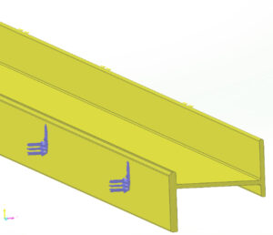
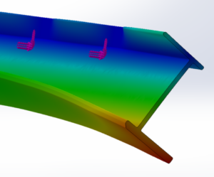
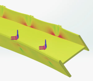
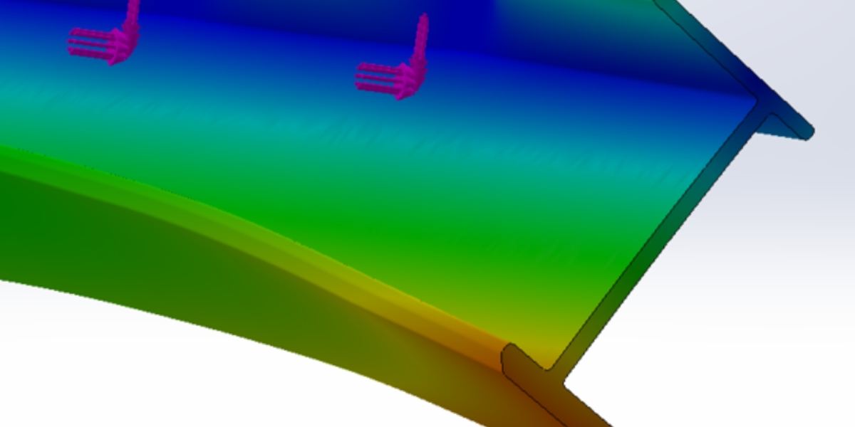
Figure 1: Left, a butt joint cantilever is shown at the end of an FRP Z-shaped subframe. Middle, the torsional effects are shown for deflection after wind and dead loads are applied. Right, the torsional effects are shown for stress after wind and dead loads are applied.
Guidelines for Accurate Finite Element Analysis (FEA):
Although both steel and FRP can be used structurally within the building envelope, they must be analyzed differently when it comes to finite element analysis. Complexities including orthotropic analysis, point loading, stress concentrations, and cantilevers must all be considered when performing a structural analysis on FRP.
The following general guidelines are necessary to accurately model structural components or systems:
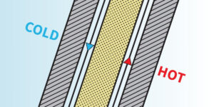
- Orthotropic Analysis – Because the properties of FRP can vary greatly in different directions, an orthotropic analysis must be used. This type of analysis is more complex than a usual isotropic analysis and considers the different directional properties of the material.
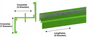
Figure 2: Property Directions for Orthotropic Materials
- Point Loading – Cladding options like stucco may result in uniform loading, but most claddings used with FRP sub-structures must utilize point loading to get the most accurate structural results. Point loads should be placed at a worst-case location, most likely midway between the attachments of the FRP sub-structure to the substrate. This will result in worst-case stress concentrations, providing a more realistic model for what is occurring on the actual wall.
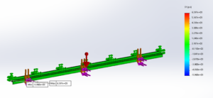
Figure 3: FEA with Point Loading
- Non-Bonded Contacts – It is important to use non-bonded contact sets when modeling FRP components. This will prevent the model from being too rigid and will more accurately reflect the behavior of the material.
- Mesh – When creating a mesh for an FRP model, it is important to use a curvature-based mesh. This will result in the largest number of nodes and elements, which will provide more accurate results. By following these guidelines, you can be sure that your structural analysis of FRP components is accurate and reflective of the material’s behavior.
- Cantilevers – When modeling a cantilever, it is important to use a worst-case scenario. This means that the maximum cantilever between spans should be used. For example, if the span is 16″, a cantilever of 15″ should be used. This will provide a realistic design for what will occur when the FRP substructure is utilized on the wall.
- Fastener Placement – In general, fastener spacing and edge distance in FRP are as follows: 1) For center-to-center spacing of fasteners, at least 5 times the fastener diameter, 2) From the edge of the profile (along the profile), fasteners should not be placed closer than 2.5 times the fastener diameter, 2) From the end of the profile, fasteners should not be placed closer than 3 times the fastener diameter. This will help avoid fastener stress concentrations.
By following these guidelines, you can be sure that your structural analysis of FRP components is accurate and reflective of the material’s behavior.
Final Checks
- Any FEA or set of calculations should be reviewed or performed by the professional engineer doing the cladding assembly calculations. Only a Professional Engineer with knowledge of FRP should sign off on the settings and results provided by the FEA. The FEA analysis must include the following items: validation of mesh size, loading model, and boundary support model.
- Provide FEA to replicate and evaluate areas of the longest FRP girt cantilever span possible between intermediate framing members/attachment.
- Butt joints should be installed on a minimum surface width of 3″ or double stud condition to accommodate proper fastener margins to FRP.
Conclusion
When designing with FRP, it is important to consider all aspects of the material to create a safe and effective structure. This includes understanding how to properly analyze the structural loading of FRP Z-shaped sub-framing. By following best practices, like FEA, accounting for point loads, etc., and consulting with a professional engineer, you can ensure that your FRP structure will be able to withstand the specified loads for each project.
Footnotes:
- While most projects cannot use uniform loading, there are specific situations where it can be used. Best practices should be used for this decision.
- Cantilevers are less of a concern when a splice joint is used to connect adjacent Z-shapes.
*Information listed is based upon the material samples available in the marketplace and datasheets from materials available at the current time of testing. Data listed is not considered all-inclusive for materials from other market spaces or other applications.
Download the full Engineering Study on Structural Loading of FRP Z-Girt Sub-Framing below.
© 2022 Advanced Architectural Products
Our A2P Representatives and in-house Engineers are ready to discuss your next project. Contact us today to get started.