
The Problem: The assumption of uniform loading across structures is a common but flawed practice that can lead to significant safety and trailing liability issues.
I. Introduction
A widespread yet misleading approach in construction is the assumption that a building’s cladding load is uniformly distributed across its structure. This oversimplification can usher in considerable liability and safety concerns down the line. Highlighting a critical yet frequently overlooked element of structural integrity–tributary area–this article seeks to unpack the complexities of load distribution. Understanding tributary areas involves calculating the specific weight load that different parts of a building’s framework are responsible for supporting. This is crucial, regardless of the materials involved, whether it be stucco, stone, or more intricate options such as Aluminum Composite Material (ACM) and metal plates.
The distinction between evenly spreading weight throughout the entire framework and concentrating it on particular points is vital to prevent excessive stress on any part of the structure. Through a detailed exploration of how precise the tributary area analysis enhances load distribution, this discussion aims to elevate our buildings beyond mere aesthetic appeal, ensuring they are both structurally sound and durable.
II. The Concept of Tributary Area
In construction, the tributary area is vital for designing buildings that are both stable and efficient. It is about calculating, how the weight is distributed across the structure to avoid unnecessary stresses on any part of the frame.
Definition and Importance
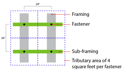
The tributary area refers to the specific portion of a building supported by a structural element, such as a beam, column, or fastener. This concept is key to understanding how much weight each part of the structure needs to support, ensuring that no component is overloaded.
Calculating Tributary Area
For example, consider a clip support spacing 24″ x 24″ on a wall frame. By multiplying the space dimensions (24″ x 24″), it has a tributary area of four square feet, meaning it supports the load within this area. If two fasteners are used per four-square-foot tributary area, the load is divided, giving each fastener a tributary area of two square feet.
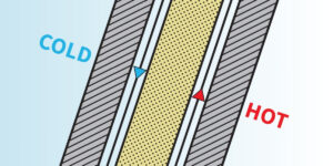
Tributary Area and Eccentric Loads
The calculation becomes more complex with eccentric loads, which occur when cladding is not uniformly attached, leading to uneven stress distribution. This necessitates careful consideration in the design to ensure the sub-framing can adequately support the building without compromise.
Understanding and correctly applying the principles of tributary areas and eccentric loads are crucial in construction. This knowledge ensures that structures are designed to withstand various stresses, ensuring their longevity and safety.
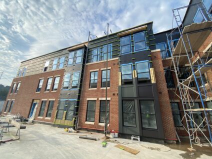
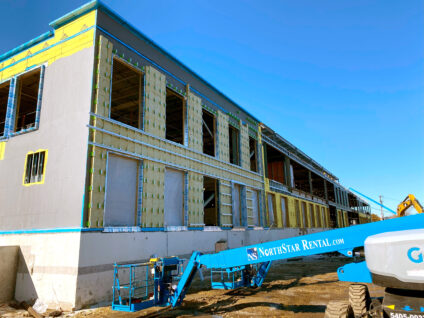
III. Challenges with Different Cladding Types
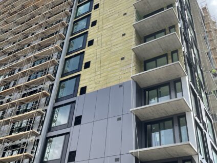
Choosing the right cladding is critical because it influences the structural requirements of a building. Whether it is traditional materials like stucco and stone or modern ones like ACM or metal plates, each option distributes weight and external forces differently across the building’s structure.
Uniform vs. Point Loading
Uniform loading evenly spreads the cladding’s weight and forces (like wind or snow) across the structure, commonly with materials such as stucco or adhered stone. Point loading, associated with ACM and metal plates, focuses stress on specific points of attachment, leading to higher stress areas on the frame.
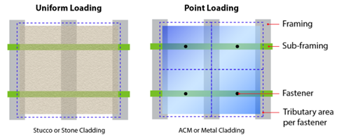
Challenges with ACM and Metal Plate Cladding
ACM and metal plate cladding can pose distinct challenges due to their specific attachment methods, which often concentrate stress at certain points of the frame. For instance, a 4′ x 12′ ACM panel weighing 144-pounds does not distribute its weight evenly. Design considerations must include the increased load on each fastener, especially in conditions like high winds, which can amplify stress.

The Necessity of Precise Analysis
Conducting an engineering analysis is vital to avoid underestimating stress on composite sub-frames, particularly with claddings like ACM and metal plates that create large point loads. Engineers need to use comprehensive calculations and simulations to understand how cladding affects the structure. This ensures buildings are safe, functional, and durable.
Choosing cladding impacts more than a building’s appearance; it significantly affects structural design and stability. With thorough analysis and engineering, the complexities introduced by different cladding materials can be managed, supporting the success of construction projects.
IV. Perimeter Loading and Its Effects
Every detail in the design phase is critical, right down to how the weight of different materials is supported by the structure. One such detail, perimeter loading, plays a significant role, especially in modern designs that feature materials like ACM panels and metal plates.
Understanding Perimeter Loading
Perimeter loading directs structural stress to the edges of materials, which is common in cladding that attaches at the boundaries. This method significantly impacts how the load is carried by the building’s framework.
The Impact of Tributary Areas
With perimeter loading, the tributary area for each support element increases as loads are focused on the edges. This can lead to larger tributary areas at points where the composite sub-framing meets the cladding, especially in larger panels. Understanding these areas is vital to ensuring permanent fastening.
Tackling the Design Challenges
Overcoming the challenges of perimeter loading involves strengthening the sub-framing system to handle increased loads and using materials with higher load-bearing capacities. Advanced simulation tools also play a role, allowing engineers to anticipate how a structure will fare under various loads and adjust designs accordingly.
By addressing perimeter loading and its impact, engineers and architects can create structures that are both visually striking and structurally robust, ensuring they endure over time.
V. Optimizing Load Distribution: A Case Study on ACM Panel Installation
The installation of Aluminum Composite Material (ACM) panels illustrates the complexities of load distribution, which is essential for maintaining structural integrity. Despite their lightweight nature, ACM panels pose distinct challenges due to their attachment methods.
The ACM Panel Example
Consider a 4′ x 12′ ACM panel weighing approximately 144-pounds, designed to attach only along its perimeter. This design choice significantly affects load distribution across the structure. Assuming the panel is supported by a horizontal girt spaced at 24″ on center, around 18 ACM clips would be needed. Factoring in environmental loads, like a +40/-70 PSF ultimate wind load, each fastener must withstand up to 224-pounds of point load from the wind, placing high demand on both the fasteners and the composite girts.
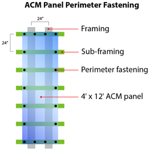
A uniform loading assumption would inaccurately spread an allowable load of 336-pounds over the four-foot span where the girt attaches to the panel, misrepresenting the actual load distribution.
Design Considerations for Structural Integrity
- Sub-Framing Capacity: Composite girts need to be designed to handle the concentrated loads from perimeter attachments, ensuring they support additional forces without risking the structure’s stability.
- Fastener Durability: It is imperative that fasteners are selected and designed to bear the expected maximum loads, including additional stresses from environmental factors. Focused loads are not ideal for composite-only girts due to the possibility of micro-fractures and susceptibility to pull-out.
- Accurate Load Analysis: Engineers must perform detailed calculations, moving beyond uniform loading and assumptions to accurately reflect scenarios like point and perimeter loading seen with ACM panels.
- Safety and Efficiency: Accurate analysis is key to ensuring the building’s safety and the durability of its structure while also achieving cost efficiency but avoiding over- or under-engineering.
This case study highlights the need for careful load distribution analysis in the design and installation of cladding systems, particularly those involving unique materials like ACM cladding panels and composite sub-framing. By addressing these challenges, engineers and designers can create buildings that are both visually appealing and structurally robust.
VI. Best Practices in Sub-Framing Design
Achieving longevity and safety in buildings hinges on the detailed design of sub-framing systems that support cladding. Effective load distribution involves solid engineering, advanced software, and compliance with industry standards.
Engineering Approach to Optimize Load Distribution
A comprehensive analysis of loads, including the weight of cladding and environmental factors like wind and seismic activities, is fundamental. This ensures the composite sub-framing can withstand all stresses.
Using Advanced Software
Modern engineering utilizes sophisticated software for accurate load calculations and design optimization.
- Finite Element Analysis (FEA) Software: Enables detailed simulations to identify design weak points.
- Building Information Modeling (BIM) Tools: Supports a collaborative design process, integrating data on every building component.
- Load Calculation Software: Assists in ensuring designs can support intended loads effectively.
Adhering to Industry Standards and Guidelines
Adhering to industry standards ensures sub-framing designs are safe and effective:
- International Building Code (IBC): Provides essential codes for building design and construction.
- American Society of Civil Engineers (ASCE) Standards: Offers guidelines on structural design and load calculations.
- ASTM International Standards: Covers materials and techniques for optimal sub-framing design.
By integrating thorough engineering practices, leveraging technology, and following industry standards, engineers can develop sub-framing systems that combine functionality, aesthetics, and durability.
VII. Conclusion
The key to building enclosure designs that endure over time is accurately understanding and calculating tributary areas. This essential aspect of design ensures optimal load distribution on sub-framing and building enclosure designs, which is important for both structural efficiency and overall safety.
With a variety of cladding materials in use, precise engineering is vital to address their specific load requirements. Any inaccuracies can result in construction failures, posing risks to both finances and, more critically, human lives. Therefore, meticulous calculations and a comprehensive grasp of tributary areas are fundamental to maintaining building safety and longevity.
As the field of construction evolves, so too should our approaches and methodologies. Embracing ongoing education and adoption of new technologies is imperative for tackling the complex engineering challenges of today and tomorrow. By committing to this continual learning process, we ensure that our structures not only meet the current standards but are prepared to withstand future demands.
VIII. Enhancing Sub-Framing with GreenGirt CMH and SMARTci Systems: The Advanced Architectural Products Advantage
GreenGirt composite metal hybrid (CMH) continuous insulation and SMARTci building enclosure systems by Advanced Architectural Products (A2P) significantly surpasses composite-only sub-framing systems, setting a new benchmark in construction. Unique to GreenGirt CMH and SMARTci is its incorporation of continuous interlocking metal backer plates in both flanges, a design choice that revolutionizes load distribution and fastener retention.
This design not only facilitates an even spread of loads across the sub-framing, catering to the demands of diverse cladding materials, but also ensures an exceptional increase in fastener retention compared to composite-only sub-frames. The structural resilience offered by GreenGirt CMH and SMARTci systems is unparalleled, making them the optimal choice for projects aiming for the highest standards of safety and durability.
Further distinguishing Advanced Architectural Products is their commitment to precision, quality assurance, and an engineering review. Every project utilizing the GreenGirt CMH continuous insulation or SMARTci building enclosure systems undergoes a comprehensive Finite Element Analysis (FEA). This process ensures that each installation is optimized for specific structural requirements, offering tailored solutions that address the unique challenges of tributary areas and point loading.
By integrating GreenGirt CMH or SMARTci into your project, you are not just choosing a superior sub-framing system; you are also benefiting from Advanced Architectural Products’ dedication to engineering excellence. A2P’s proactive approach, utilizing FEA analysis for every project, exemplifies commitment to delivering structurally sound and efficient building enclosure solutions. This makes GreenGirt CMH and SMARTci not just products, but a comprehensive solution for modern construction needs.
If you are interested in learning more about Advanced Architectural Products, GreenGirt CMH continuous insulation or SMARTci building enclosure systems, visit our website or contact us today!
© 2024 Advanced Architectural Products